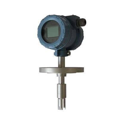
Digital pressure transmitters are divided into diffusion silicon pressure transmitter cores and capacitive pressure transmitter cores. The diffused silicon pressure transmitter has the advantages of reliable operation, stable performance, convenient installation and use, small size, light weight, and high cost-effectiveness. Digital pressure transmitters are widely used in oil field pipeline transmission, boiler heating pipeline data collection, and chemical pipeline data collection. There are two convenient and versatile options for indoor and outdoor use, and we can distinguish their quality through the following methods!
Method 1: Inspection of the measurement part of the digital pressure transmitter. Any malfunction caused by the measurement part of the transmitter can cause the transmitter to have no output or abnormal output. Therefore, the sensitive components of the transmitter should be checked first. Remove the flange and inspect the sensitive component isolation diaphragm for deformation, damage, and oil leakage.
Remove the compensation board without removing sensitive components. Check the insulation resistance of the contact pin to the housing. When the voltage does not exceed 100V, the insulation resistance should not be less than 100M Ω. Connect the circuit and gas circuit, and when the pressure signal is at the upper limit of the range, turn off the gas source. The output voltage and reading value should be stable. If the output voltage drops, it indicates a leak in the transmitter. Soap water can be used to check the leak location.
Method 2: Check the circuit of the transmitter. Connect the power supply and, after giving the input pressure signal, check the status of the voltage signal at the output end of the transmitter. If there is no output voltage, first check whether the power supply voltage is normal; Whether it meets the power supply requirements; Check for any wiring errors between the power supply, transmitter, and load equipment. If there is no voltage or polarity reversal on the transmitter wiring terminal, it can cause the transmitter to output no voltage signal.
To eliminate the above reasons, further inspection of the components in the amplifier board circuit should be carried out for any damage issues; If there is any poor contact phenomenon in the circuit board connector, the method of comparing the measured voltage of the normal instrument with the corresponding measured voltage of the faulty instrument can be used to determine the fault point. If necessary, the faulty amplifier board can be replaced. When inspecting flow type transmitters, special attention should be paid to taking anti-static measures for the J-type amplifier board.