As a supplier of Turbine Flowmeters, I am often asked about the signal processing methods of these devices. Turbine flowmeters are widely used in various industries to measure the flow rate of liquids and gases. They operate on the principle that the rotation speed of a turbine placed in the flow path is proportional to the flow rate. The key to accurately measuring this flow lies in effectively processing the signals generated by the turbine's rotation.
Basic Working Principle of Turbine Flowmeters
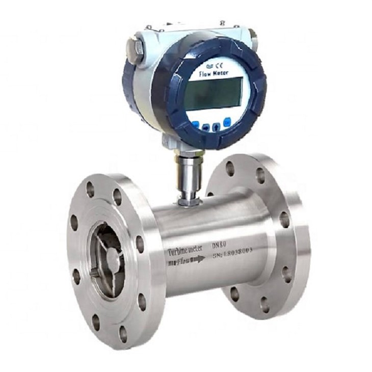
Before delving into the signal - processing methods, it is essential to understand the basic working mechanism of a turbine flowmeter. When a fluid (liquid or gas) passes through the flowmeter, it causes a turbine rotor to spin. The rotational speed of the turbine is directly related to the velocity of the fluid flowing through the meter. As the turbine rotates, it generates a series of pulses or electrical signals that need to be processed to obtain an accurate measurement of the flow rate.
Signal Generation in Turbine Flowmeters
The signal generation in turbine flowmeters typically involves the use of sensors. There are mainly two types of sensors commonly used: magnetic sensors and optical sensors.
Magnetic sensors are based on the principle of electromagnetic induction. The turbine blades are made of a ferromagnetic material or are equipped with small magnets. As the turbine rotates, the magnetic field around the sensor changes, inducing an electrical voltage in the sensor coil. This voltage is then converted into a series of electrical pulses, with the frequency of the pulses being proportional to the rotation speed of the turbine.
Optical sensors, on the other hand, use a light source and a photodetector. The turbine blades interrupt the light beam between the light source and the photodetector. Each interruption generates a pulse signal. Optical sensors are often used in applications where high - precision measurement is required, especially in clean fluid environments.
Signal Processing Steps
Signal Conditioning
The first step in signal processing is signal conditioning. The raw signals generated by the sensors are often weak and may contain noise. Signal conditioning involves amplifying the weak signals to a suitable level for further processing. It also includes filtering out unwanted noise and interference. For example, low - pass filters can be used to remove high - frequency noise, while notch filters can be employed to eliminate specific frequencies of interference.
Frequency Measurement
Once the signals are conditioned, the next step is to measure the frequency of the pulses. This frequency is directly related to the flow rate of the fluid. There are several methods for frequency measurement.

One common method is the direct counting method. In this method, a counter circuit counts the number of pulses within a specific time interval. The frequency is then calculated by dividing the number of counted pulses by the time interval. This method is relatively simple and is suitable for applications with a relatively stable flow rate.
Another method is the period measurement method. Instead of counting the number of pulses, this method measures the time interval between consecutive pulses. The frequency is then calculated as the reciprocal of this time interval. The period measurement method can provide higher accuracy, especially at low flow rates.
Flow Rate Calculation
After obtaining the frequency of the pulses, the flow rate can be calculated. The relationship between the frequency (f) and the flow rate (Q) is given by the equation:
[Q = K\times f]
where K is the meter factor. The meter factor is a calibration constant that is determined during the calibration process of the flowmeter. It takes into account factors such as the geometry of the turbine, the properties of the fluid, and the characteristics of the sensor.
Output and Display
The final step in signal processing is to output and display the calculated flow rate. The flow rate can be output in various forms, such as analog signals (e.g., 4 - 20 mA), digital signals (e.g., Modbus, Profibus), or as a visual display on a local panel.
Applications and Different Types of Turbine Flowmeters
Turbine flowmeters are used in a wide range of industries. For example, in the food and beverage industry, Milk Turbine Flowmeter is used to measure the flow of milk and other dairy products. These flowmeters need to meet strict hygiene standards and often use special materials and designs to ensure the quality and safety of the products.
In the energy sector, Natural Gas Turbine Flowmeter is widely used to measure the flow of natural gas. They need to be able to operate accurately under high - pressure and high - temperature conditions.
In the pharmaceutical and biotechnology industries, Tri - clamp Turbine Flowmeter is often used. The tri - clamp design allows for easy installation and cleaning, which is crucial in these industries where strict cleanliness and sterility are required.
Advantages of Our Turbine Flowmeters
As a supplier, we take pride in the quality and performance of our turbine flowmeters. Our flowmeters are designed with high - precision sensors and advanced signal - processing algorithms. This ensures accurate and reliable flow measurement in various applications.
We also offer customized solutions to meet the specific needs of our customers. Whether it is a special material requirement, a specific output format, or a unique installation condition, we can provide a tailored solution.
Contact Us for Purchase and Negotiation
If you are interested in our turbine flowmeters or have any questions about their signal - processing methods, please feel free to contact us. We are always ready to provide you with detailed information and support. Our team of experts can assist you in selecting the most suitable flowmeter for your application and guide you through the entire purchasing process.
References
- ISO 9951:2019, “Measurement of fluid flow in closed conduits - Turbine meters”.
- Spitzer, D. W. (2016). “Flow Measurement: Practical Guides for Measurement and Control”.
- Miller, R. W. (1996). “Flow Measurement Engineering Handbook”.